Saturday, July 31, 2021

1950 Plymouth Deluxe Wiring Diagram

It was meant to be entry-level affordable but boasted of features far beyond what any in the competition could offerhydraulic brakes being one of them. 1946 1947 1948 1949 1950 1951 1952 1953 1954 PLYMOUTH FACTORY REPAIR SHOP SERVICE MANUAL BODY MANUAL P-19 Deluxe P20 Deluxe Special Deluxe P22 Concord and.

1951 Chevy Deluxe Ignition Wiring Fisher Plow Joystick Wiring Diagram For Wiring Diagram Schematics

Wiring for 1941 Ford Car.

1950 plymouth deluxe wiring diagram. The Plymouth Deluxe was a product of an odd marketing strategy by Chrysler. 1950 PLYMOUTH DELUXE 3 SPEED TRANSMISSION FLAT HEAD SIX CYLINDER. Plymouth 1950Deluxe P19Deluxe SpecialDeluxe P200001.

Lower Front Fender Repair Sections for 1949 1950 Plymouth All Plymouth Models. The Ranco Heater Control Valve was very popular and used on many makes and models in the 1950s and early 1960s. To find tdc for 1 plug.

Through CHRYSLER New Yorker Deluxe Series C. Wiring for 1942 Ford Car. Buy now to own the best manual for your vehicle.

Classifieds for 1950 Plymouth Vehicles. Wiring diagram for 1952-54 Ford 6 Wiring diagram for 1952-54 Ford 8. -Vehicle is on consignment and at our clients home -Please Call First and.

Easy to use parts catalog. 1942 P14-S DeLuxe 15135501 15153935 22037001 22041356 3134501 3136266 1942. Where rotor is pointing is 1.

1795 481 shipping. This book has 254 pages measures 85 x 11 and is 069 thick. Plymouth 1936 Standard P1Deluve P2 Plymouth 1937 Standard P3Deluxe P4.

40 out of 5 stars 2 ratings. RockAuto ships auto parts and body parts from over 300 manufacturers to customers doors worldwide all at warehouse prices. 1950 Plymouth Car Color Wiring Diagram.

1950 Plymouth Vehicles for Sale. 1950 Plymouth Deluxe Wiring Diagram It is far more helpful as a reference guide if anyone wants to know about the homes electrical system. Its components are shown by the pictorial to be easily identifiable.

Instantly Download Over a thousand wiring diagrams for 187 models. Is the least efficient diagram among the electrical wiring diagram. AntiqueCarDiagramsCom has one of the largest collection of antique car wiring diagrams on the internet.

Need sparkplug wiring diagram fo 1950 flathead 6 dodge firing order is 1-5-3-6-2-4 plug gap is 035. Free shipping on many items Browse your favorite brands affordable prices. The Deluxe enjoyed only a short four-year production run but those were four truly amazing years.

480-285-1600 email protected 1345 East Chandler Blvd. Wiring for 1940 Standard Ford Car. Wiring for 1939 Deluxe Ford Car.

Wiring for 1940 Deluxe Ford Car. Make sure this fits by entering your model number. 15 results per page.

Also be sure to view results in. Bring number 1 cylinder all the way to top. NOS PN 1340312 amp meter for 1950 Dodge Coronet - Meadowbrook - Wayfarer NOS PN 1340339 - 1369698 amp meter for all 1950 Plymouth Deluxe - Special DeLuxe - Suburban.

This fits your. 10 OUTER BODY PANELS - CONTINUED Lower Front Quarter Panel Repair Section Bottom View. Plymouth 1935 Deluxe PJEconomy PJ E Plymouth 1935 Standard Models.

New listings are added daily. Sign in to follow this. Wiring diagram for 1950 Ford.

NEW TIRES NEW UPHOLSTERY WOULD DRIVE IT ANYWHERE. With over a thousand wiring diagrams for 187 models of antique cars ranging from 1912 - 1956 we have made sure we have everything you are looking for. For 1950 dodge 230 inline six.

6 vehicles matched Now showing page 1 of 1. 1950 Plymouth Car Color Wiring Diagram. I decided to add this content here because it is an integral part of the Deluxe Heater System.

This manual covers all 1946-1951 Plymouth Deluxe Special Deluxe models including Sedan Coupe Club Deluxe Convertible Suburban Wagon P-15 P17 P18 P19 P20 P22 P23. Wiring diagram for 1951 Ford. This Heater Control Valve is designed to add a passive thermostatic control feature to the system.

1934 Plymouth Deluxe PE Color Wiring Diagram Complete basic car included engine bay interior and exterior lights under dash harness starter and ignition circuits instrumentation etc Original factory wire colors including tracers when applicable Large size clear text easy to read. DOWNLOAD 1950 Chrysler Windsor Ignition Wiring Diagram. If you need your diagrams in 5-6 days please select UPS at checkout.

Full Color Laminated Wiring Diagram FITS 1950 Plymouth Car Large 11 X 17 Size Brand. Plymouth Ignition Wiring Diagram Switches CHRYSLER C ROYAL WINDSOR EXTERIOR BODY. Back to main menu 1934-1949.

We have negotiated a flat rate of 995 per shipment. Ammeter for 1951 Chrysler Saratoga - Windsor Ammeter for 1951-1952 Dodge Passenger Cars. ELectrical Wiring Diagram Chrysler Windsor.

1795 1 review Write a Review Write a Review Close 1950 Plymouth Car Color Wiring Diagram.

Ethernet Wiring Diagram For Isdn

Ethernet Cable Wiring Diagram. It was introduced commercially in 1989 and became IEEE Standard 8023 in 1983.

Icones De Reseau Cisco Networking Infographic Network Switch Cisco

Heres a step-by-step guide to wiring your home with Cat5e or Cat6 ethernet cable.

Ethernet wiring diagram for isdn. It is designed to carry voice data images video everything you could ever need. The jack should have a wiring diagram or designated pin numberscolors to match up to the color code below. Pin 5 White and Blue wire.

It is a design for a completely digital telephonetelecommunications network. Its based on 64Kbps digital Communication channel. All devices connecting to an Ethernet router must possess a working Ethernet network adapter.

Remember that Pin 1 is on the left hand side of the RJ45 connector with the clip at the rear. Pinout of Ethernet 10 100 1000 Mbit cat 5 cat 5e and cat 6 network cable wiringNowdays ethernet is a most common networking standard for LAN local area network communication. Many but not all wired network routers allow up to four devices to be connected using Ethernet cables.

Should you need to make one of these cables up please use the diagram below as a reference. Usually this is the case when an ISDN line is provided from a Phone System. This cable is defined in TIAEIA-568-B.

It is used for data networks employing frequencies up to 16 MHz. Pin 4 Blue wire. The cable is called wipe patch cord straight-thru cable.

This post is republished from Instructables. RJ45 pinout diagram shows wiring for standard T568B T568A and crossover cable. Note that while computer 10baseT and ISDN connectors and cable are the same the pairs are different.

If youre not sure of the difference between the two check out. Profinet Wiring Diagram Wiring Connection Line M12 Jack Straight Rj45 Plug Straight 4 Pole D. If you are an existing customer and have questions about your wiring or connection please call 780-450-6787 email.

The above diagram shows an Ethernet crossover cable pin out for reference. Pin 8 Brown wire. Recall that there are two standards for the colors in the RJ45 specification.

Ethernet Cable Color Coding Diagram for. It is the form of wiring that is used for standard telephone POTS wiring or for ISDN. ISDN distribution uses standard RJ45 8 way sockets as used for Ethernet 10baseT networks.

Youll love our internet and hosting services. To be honest I dont know if either would work. In modern structured wiring Cat5e or Cat6 is commonly used in homes and buildings.

Og Rj45 Wiring Diagram Example Wiring Diagram M12 Versus Rj45 Ethernet Connections On The Factory Floor How To Wire A Rj45 Plug Onto Cat5 Cable Hd Youtube. Do not use an Ethernet or Network crossover cable as these are different to an ISDN crossover cable. Care should be taken.

Pin 6 Orange Receive - wire. The Cat 5e and Cat 6 data lines are often used for both voice or data. Pin 3 White and Orange Receive wire.

This diagram illustrates the use of a wired network router as the central device of a home network. When wiring a jack or an RJ-45 plug remember to keep the twist as close as possible to the jack or plug receptacle. Pin 7 White and Brown wire.

CLICK to find view print and more. The color codes above are the standard and defined within. This is not recognised by theTIAEIA.

A wiring diagram is a streamlined conventional pictorial depiction of an electrical circuit. This article shows how to wire an Ethernet jack RJ45 wiring diagram for a home network with color code cable instructions and photosand the difference between each type of cabling crossover straight through Ethernet is a computer network technology standard for LAN Local area network. It reveals the parts of the circuit as simplified shapes and the power as well as signal connections in between the devices.

I have seen A used for ISDN before but in looking at the T568B color guide I recognized it as the same as the tons of patch cables I have made before so I went with it. It shows the elements of the circuit as simplified shapes as well as the power as well as signal connections between the devices. Ethernet Wiring 8P8C often incorrectly called RJ45 For a normal cable you can use either T568A or T568B as long as you use.

It was the form of wiring that was used for 4Mbits token ring networks. ISDN is a generic term for any network which connects homes and business together with a service companies such as bank air-lines stock market etc using a digital network. The standard being utilized on either side of a Twisted Pair wire is what determines whether the cable is straight-through or crossover.

Variety of ethernet cable wiring diagram pdf. Collection of convert rj11 to rj45 wiring diagram. Remember the RJ45 wiring order.

RJ45 Ethernet Cable Pinout. It is also designed to provide a single interface in terms of both hardware and. This will insure compliance with Ethernet wiring standards.

Most patch panels and jacks have diagrams with wire color diagrams for the common T568A and T568B wiring standards. A wiring diagram is a streamlined traditional pictorial depiction of an electric circuit. CLICK to check the right one for you or print as reference.

ISDN is a network concept providing a integration of data voice and video. THE complete Ethernet pinout cable wiring reference with wiring step-by-step guide. ISDN stands for Integrated Services Digital Network.

The ethernet cable used to wire a RJ45 connector of network interface card to a hub switch or network outlet.

Single Phase Magnetic Starter Wiring Diagrams

A2 - 14 - 18. Wiring of the Direct-On-Line DOL Motor Starter 1 Three Phase Supply 230Volt Coil - see wiring diagram.

Single Phase Motor Contactor Wiring Diagram Elec Eng World Electrical Wiring Electricity House Wiring

A complete guide of single phase induction motor wiring connection with magnetic contactor or stater.

Single phase magnetic starter wiring diagrams. This type of motor is designed to provide strong starting torque and strong running for applications such as large water pumps. In the above one phase motor wiring i first connect a 2 pole circuit breaker and after that i connect the supply to motor starter and then i do cont actor coil wiring with Normally Close push button switch and Normally Open push button switch and in last i do connection between capacitor. Capacitor start capacitor run induction motors are single phase induction motors that have a capacitor in the start winding and in the run winding as shown in figure 12 and 13 wiring diagram.

Shut OFF the main power disconnect before starting installation. 2 Troubleshooting the Installation WARNING. It reveals the parts of the circuit as simplified shapes and the power and signal links between the gadgets.

Thermal Magnetic Single Phase 3-Phase Squirrel Cage 2-Phase 4-Wire Wound Rotor Armature Shunt Field show 4 loops. Magnetic contactor wiring diagram single phase. Type S AC Combination Magnetic Starters58-59 Class 8538 and 8539 58-59 3-Phase.

Typical Starter Wiring. 1 phase motor starter wiring diagram Full Size of Wiring Diagram Three Phase Electrical Wiring Diagram Beautiful Ponent Single Phase Motors. The above diagram is a complete method of single phase motor wiring with circuit breaker and contactor.

13 - 17 with a flying lead to be connected to Overload terminal 95. Wiring Diagram Sheets Detail. Wiring for 115-208230V single-phase circuit Wiring for 208230-460V three-phase.

Wiring Diagram Book A1 15 B1 B2 16 18 B3 A2 B1 B3 15 Supply voltage 16 18 L M H 2 Levels B2 L1 F U 1 460 V F U 2 L2 L3 GND. Firstly the stator winding is connected in star an. Dol starter control diagram three phase.

This diagram is for single-phase motor control. A-Amber R-Red R G-Green B-Blue T1 T2. A star-delta is used for a cage motor designed to run normally on the delta connected stator winding.

The overload relay is designed so the current to the motor is shared between phases so if you only wire up one phase then all the motor current goes through one of the contacts on the overload and you can. The wiring diagram is a little unclear in the box and i dont want to burn the magnetic starter is furnas the motor is a baldor t 5 hp 3wiring instructions for magnetic starters important if the compressor has a factory mount ed magnetic starter the starter has been wired to the pressure switch and motor. It may also be wired for 120 volts.

3ph Starter3ph Motor Line Voltage Control three phase 3ph motor starter controlling a three phase motor rev 08 Aug 2006 The above wiring diagram assumes your magnetic starter has a 240V coil. The people providing this information may or may not be providing completely accurate information. The start and stop circuits could alternatively be controlled using a PLC.

A wiring diagram is a simplified traditional photographic representation of an electric circuit. Single Phase Motor Overload Protection. Collection of single phase motor starter wiring diagram.

Wiring Instructions for Magnetic Starters IMPORTANT If the compressor has a factory mount-ed magnetic starter. Use the wiring diagrams on the back of this sheet to install and connect power wires for the starter. It uses a contactor an overload relay one auxiliary contact block a normally open start pushbutton a normally closed stop pushbutton and a power supply with a fuse.

Magnetic Starter Wiring Diagrams for 30 Amp 120240 Volt Coils. Wiring Instructions for Magnetic Starters IMPORTANT If the compressor has a factory mount-ed magnetic starter. Improper wiring can Kill Injure Start Fires Burn Out Motors or anyall of the above.

Fig 4 Illustrates how to wire the magnetic starter to the motor and pressure switch For further Information on magnetic starters refer to Form 200-1946 WARNING. 1 The following links are pre-fitted to the starter. Single phase motor starters are not commonly available since this is a rare case and with a little bit of know how a 3 phase motor starter can easily be wired for.

Previously we discussed what a magnetic motor starter is a contactor and an overload relay. This Magnetic Starter is a 3 phase full voltage across the line starter with the coil factory wired for 208-240 volts Figure B. Standard Diagram Symbols Coils Single Voltage Magnet Coils Dual Voltage Magnet Coils Contacts Normally Open Normally Closed Timed Open Timed Closed Fuse Standard Indicator Lights Standard Motors AC Single-Phase Three-Phase Link High Voltage 12 34 Links Low Voltage 1234 TO.

All other control and power connections have to be made by the installer. The main and standbyemergency power supplies the neutrals of the two systems must be separated to assure proper ground fault current sensing.

Ford Flex Wiring Diagrams Pdf

Im going to ground it to make the computer think the door is always closed. 73 Torino Wiring Diagram - in a PDF file.

Engine Diagram 5 Jetta Power Taurus Ford Diagram

69 MUSTANG WIRING DIAGRAM-2 - Drawing B.

Ford flex wiring diagrams pdf. 2011 Ford Flex SEL EB. The 2019 Ford Flex service manual PDF delivered by us it contains the repair manual parts manual and wiring diagrams in a single PDF file. 2011 Ford Flex Titanium Sport Utility 4-Door.

Model-Years Application 2011 Ford Flex Limited Sport Utility 4-Door. All that you ever need to drive maintain and repair your 2019 Ford Flex. NUD105-R025E Ford Flex Probe Kit Avoid damaging the vehicles electrical connections.

2019 Ford Flex repair manual. Some ford car service manuals pdf wiring diagrams are above the page. Wiring Diagrams 2011 Flex Wiring Diagrams.

NUD105-R025E Ford Flex Probe Kit Avoid damaging the vehicles electrical connections. Theres lots more information. NUD9000-001 NUD900-002 NUD900-003 and NUD105-R025E Flex Probe Kit are available through RTTP.

2011 Ford Flex SE Sport Utility 4-Door. 2012 Ford Flex 2011 Ford Flex 2010 Ford Flex 2009 Ford Flex 2014 Ford Focus 2013 Ford Focus 2012. 2013 you now have the ability to repair most wiring connector issues especially in high cavity count connectors.

1987 Ford Glow Plug wiring - Drawing A. Ford Sierra Wiring Diagrampdf. 2013 you now have the ability to repair most wiring connector issues especially in high cavity count connectors.

Automotive wiring in a 2013 Ford Flex vehicles are becoming increasing more difficult to identify due to the installation of more advanced factory. Ford wiring diagram pdf. Terminal Release Tools RTTP s.

91 Ford chassis Wiring Diagram - Drawing B. The Battery Junction BoxPower Distribution Box located under the hood and the Smart Junction BoxPassenger Compartment Fuse Panel. The 2019 Ford Flex service manual PDF delivered by us it contains the repair manual parts manual and wiring diagrams in a single PDF file.

Ge__st__20 when I programmed mine. In them minibuses ford transit almost always participate. The 2019 Ford Flex repair manual.

Terminal Release Tools RTTP s. NUD900-001 NUD900-002 NUD900-003 and NUD105-R025E Flex Probe Kit are available through RTTP. Totally Free Ford Wiring Diagrams.

Thu Jan 20 2011 730 pm. 1957 ford thunderbird wiring diagram 1960 ford falcon 6 cylinder wiring diagram 1960 ford thunderbird v8 1962 ford galaxie v8 wiring diagram 1964 mustang master wiring locator diagram 1965 ford thunderbird convertible tops control diagram 1965 ford thunderbird window controls diagram 1965 mustang. The list of Ford Stereo Wiring Diagrams that were displayed here will be described in details in the link on every Ford Years and Series as mentioned below.

Some ford bus manuals wiring diagrams pdf are above thepage. Ford Truck Diagrams and Schematics. 2011 Ford Flex SEL Sport Utility 4-Door.

1984 to 86 Ford Glow Plug wiring - Drawing A. Variety of 2001 ford ranger wiring diagram pdf. Whether your an expert Ford Flex mobile electronics installer Ford Flex fanatic or a novice Ford Flex enthusiast with a 2010 Ford Flex a car stereo wiring diagram can save yourself a lot of time.

The PDF link has Ford service manual for 2007 that corroborates what the guy wrote and. Read Free 2013 Ford Flex Headlight Wiring Diagram 2013 Ford Flex Headlight Wiring Diagrampdfazapfdingbats font size 14 format As recognized adventure as well as experience practically lesson amusement as skillfully as deal can be gotten by just checking out a books 2013 ford flex headlight wiring diagram as a consequence it is not directly done you could resign yourself to even more in. 850 x 1100 x 078.

Automotive wiring in a 2010 Ford Flex vehicles are becoming increasing more difficult to identify due to the installation of 2010 Ford Flex Car Stereo Wiring Chart Read More. 2009 Ford Flex Fuse Diagram 2009 Ford Flex Fuse Diagram for Battery Junction Box and Smart Junction Box Passenger Compartment This 2009 Ford Flex Fuse Diagram shows two fuse boxes. Have watch and find the one that suit with your own Ford Automobile Years and Series.

91 Ford engine Wiring Diagram. Ford Flex S SE SEL Limited 2014 Service Repair Workshop Manual Download PDF 2014 Ford Flex Service And Repair Manual Ford Flex 2013-2015 Factory Workshop Service Repair Manual. Ford Vehicles Diagrams Schematics and Service Manuals - download for free.

Ford Orion 1990-1999 Electrical Wiring Diagrampdf. Ford S-MAX 2006 Electrical Wiring Diagramrar. Alternator Voltage Regulator Instrument Panel Starter and Drive Distributor.

91 Ford chassis Wiring Diagram - Drawing A. Easy Wire Mustang Installation Manual - in a PDF file. PDF will be created and delivered using your car VIN.

Whether your an expert Ford Flex mobile electronics installer Ford Flex fanatic or a novice Ford Flex enthusiast with a 2013 Ford Flex a car stereo wiring diagram can save yourself a lot of time. And since I didnt have the 2011 wiring diagram I didnt want to chance tapping into the subwoofer level inputs. 2011 Ford Flex SEL EB.

The 2019 Ford Flex repair manual PDF will be created and delivered using your car VIN. This item is original. Wiring diagram 2013 ford flex - fixya wiring diagram 2013 ford flex - ford 2013 flex question i dont have wiring schematics---need help - ford flex forum i need the wire color for the door ajar switch wire going to the driver door from the driver left foot kick panel area.

All that you ever need to drive maintain and repair your 2019 Ford Flex. Free download workshop manuals wiring diagrams owners and service manuals for ford cars.

Automobile Wiring Harness Manufacturers In India

Find here Wiring Harness Safety Wire Harness manufacturers suppliers exporters in India. Welcome to Sushan Enterprises Established in the year 2009 we Sushan Enterprises are engaged in manufacturing a wide range of Automobiles Parts like Main Engine Wiring Harness Bulb Connector Plug 2 Pin Dash Board Holder Solenoid Switch Switch Four Pin Power Connector Automotive Electric Cable Battery Jointer Automotive Fuse Box.

Wiring Harnesses Wiring Harness And Cable Looms Manufacturer And Exporter Hid Xenon Hide Wires Electrical Wiring Diagram

The Priya Wiree Harness India a leading and established name in manufacturing of Wiring Harness for electrical electronic auto domestic appliances and industrial application has earned high reputation in the national as well as international market by offering unique and exclusive products and services.

Automobile wiring harness manufacturers in india. These automotive wiring harness manufacturing companies provide high quality products as per your need. Get automotive wiring harness manufacturers automotive wiring harness suppliers and exporters. Darshan Auto Cable is a Professional Manufacturers of wiring harness in Hosur Krishnagiri District TamilnaduIndia.

We employ excellent quality components and other material to develop these products at par with international market standards. Find details of companies Supplying Automotive Wiring Harness Manufacturing wholesaling Auto Harness in India. We offer our clients wide variety of Wiring Harness and Auto Switches.

1 2 - C Wing Ashoka Vihar 1 st Floor XLO Corner Ambad Nashik - 422 010 Maharashtra India. Choose a safer and professional alternative. I did all the wiring as described but had no power throughout the car.

The Nova still has its original wiring except for the cables I upgraded with American Autowire. I called today and spoke to one of your Technicians. It operates from around 260 facilities in 40 countries.

Harness Techniques I Pvt. Find here Automotive Wiring Harness auto harness manufacturers suppliers exporters in India. OasisIndia wiring harness manufacturers in India We supply and manufacture electrical wire battery cables wire harness products for automotive company.

WIRING HARNESSES for Electronic Industries J K Wiring System 1 2 - C Wing Ashoka Vihar 1 st Floor XLO Corner Ambad Nashik - 422 010 Maharashtra India. Cable Ties Mounts. We provide complete support to OEMs for all types of accessories that are used to mount our cable harnesses to their equipments.

J K Wiring System. Incepted in the year 1994 Harness Techniques was established with an objective to be recognized as a leading manufacturer and exporter of Wiring Harness Automotive Wiring Harness Electrical Wiring Harness Elevator Wiring Harness with Controller DMD Cables Lead Wires etc. Our range is widely used in automobile heavy earth moving construction auto industry etc.

Besides this the company produces automotive electronics wire harnesses junction boxes terminals and connectors and body control modules. Miracle Electronics wire harness. As the name implies specializes in design and execution of wiring harnesses for appliances Auto Electrical and Electrical Applications.

We Avenue Auto Appliances Industries is an ISO 90012008 certified company and foremost manufacturers and suppliers in India of a wide range of wiring harness plastic components auto switch and others. Incepted in 2013 Astral Auto Electricals is involved in manufacturing supplying and trading of superior range of Harness. Lear Corporation is one of the leading manufacturers of seating and other related components for automobiles.

Get contact details address of companies manufacturing and supplying Wiring Harness Safety Wire Harness Cable Harness across India. We are tied up with Global manufacturers like Hellerman Tayton and many Indian manufacturers for high quality and precision products. Automotive wiring harness is an electrical assembly of various components in a vehicle that transmits power and information to a single system.

91 - 253 - 2381144 2381155. Get contact details address of companies manufacturing and supplying Automotive Wiring Harness auto harness Automobiles Wire Harness across India. Our Brands Name is 5 STAR.

Automotive Wire Harness Cable Harness Aerospace Cable Harness Manufacturer in India Bundles and stretches of electric cables interconnected overlapping with several joins and cuts is a certain recipe for disaster. I had purchased one of your engine harnesses for my 1963 Chevy II Nova and the light harness. It plays an important role in transmitting information about the operation of the vehicle sending receiving sensor signals and supplying power.

Phone 91 - 253 - 2381144 2381155. India Automotive Wiring Harness Market Outlook - 2025.

Friday, July 30, 2021

240 Volt 12 Lead 3 Phase Wiring Diagram

Thermal contacts TB white M 1 Z2 - Yellow AUX Z1 - Blue U2 - Black MAIN U1 - Red Clockwise Anti-Clockwise LN E. T1T6T7T12 T2T4T8T10 T3T5T9T 12 Lead.

Wiring Diagram For A Single Phase Motor 230 V Szliachta Org Electrical Diagram Electrical Wiring Colours Diagram

This panel is also included with metering arrangement to display parameters like current voltage energy and power.

240 volt 12 lead 3 phase wiring diagram. 3 phase motor wiring diagram 9 leads 3 Phase Motor Wiring Diagram 9 Leads Perfect Luxury 9 Lead Motor Wiring Diagram Pattern Electrical Diagram. Make the specified connections and secure the terminals in place. In order to make sure the electrical circuit is constructed.

I cannot wire it high voltage L1112 L2210 L3311 69 47 58 or it w read more. Higginbotham Phase Wiring Diagram. 240v Motor Wiring Diagram Single Phase - Collections Of Single Phase Motor Wiring Diagram with Capacitor Start Webtor Me New.

3 Phase Motor Wiring Diagram 9 Leads 3 phase motor wiring diagram 9 leads 3 phase motor wiring diagram 9 leads colors Every electric structure consists of various diverse parts. 3 Wire 220 Volt Wiring Diagram 3 wire 220 volt wiring diagram 3 wire 220 volt wiring schematic 3 wire 240 volt wiring diagram Every electrical structure consists of various diverse components. Variety of 3 phase motor wiring diagram 9 leads.

Wiring Diagram Images Detail. Single Phase Transformer Primary and Secondary wiring. 3 phase 480 volt 6 lead motor wiring diagram welcome thank you for visiting this simple website we are trying to improve this website the website is in the development stage support from you in any form really helps us we really appreciate that.

A 10 kVA transformer volt secondary is to service an 8 kVA. Wiring Diagram for Single Phase Motor Fresh Pretty Single Phase. December 13 2018 April 12 2020 Wiring Diagram by Anna R.

You should have a fully functional three phase motor at this. PART WINDING DELTA Connection. Otherwise the arrangement wont work as it should be.

Diagram DD6 Diagram DD8 M 1 LN E Diagram DD9 M 1 LN E White Brown Blue L1 L2 N SC Bridge L1 and L2 if speed controller SC is not required Diagram DD7 LN E L1 L2 N SC Z2 U2 Z1 U1 Cap. L1 to T1 L2 to T2 L3 to T3 T4 to T7 T5 to T8 and T6 to T9. On a 12-wire motor wired for high voltage ie 480V 10T 11T and 12T must be connected together but not connected to anything else.

The power in the main breaker is then given to various busbars. Diagram DD6 Diagram DD7 M 1 LN E Diagram DD8 LN E L1 L2 L3 SC Z1 U2 Z2 U1 Cap. This is a 12 lead motor not a 9 lead motor.

I have a 3 phase 120240 system with High leg. 480V 208V 3 Phase Transformer Wiring Diagram Wiring Diagram 3 Phase 6 Lead Motor Wiring Diagram Furthermore Wiring Diagram gives you 6 Lead Single Phase Motor Wiring Diagram. A volt primary transformer with a volt secondary is operated at volts regardless of whether the source is three phase 3-wire or three phase 4-wire.

May 12 2020 Wiring Diagram by Anna R. Higginbotham are dealing with. May 12 2020 Wiring Diagram by Anna R.

A 9-wire motor can only be connected. Honestly we also have been noticed that 3 wire 220v wiring diagram is being one of the most popular subject at this moment. So that we attempted to get some good 3 wire 220v wiring diagram photo to suit your needs.

208V Single Phase And 208V 3 Phase Oem Panels pertaining to 3 Wire 220V Wiring Diagram image size 486 X 342 px and to view image details please click the image. Each part ought to be set and linked to different parts in specific manner. Back Gt Galleries for Gt 6 Lead Single Phase Motor Wiring Diagram.

I need wiring diagrams for 3 phase v 12 lead 75 hp ac industrial motors. Do note that wiring the motor to a different voltage than what it is rated for may result in permanent damage. Ao Smith Electric Motor Wiring Diagram New Marathon Motors Wiring.

Higginbotham definitely learn different methods to complex problems. Replace the cover on the motor and turn on the power. Each component ought to be placed and linked to other parts in specific manner.

3 phase motor wiring diagram 12 leads 3 Phase 6 Lead Motor Wiring Diagram Elegant Awesome 12 Lead 3 Phase Motor Wiring Diagram Electrical. Depending on the voltage you have measured in the first step you should select the appropriate diagram. Each component ought to be placed and connected with other parts in particular way.

For all other SINGLE-PHASE wiring diagrams refer to the manufacturers data on the motor. Single-phase wiring diagrams always use wiring diagram supplied on motor nameplate. Product Connect a jumper between the H2 and H3 terminals and.

ALWAYS USE WIRING DIAGRAM SUPPLIED ON MOTOR NAMEPLATE. Thermal contacts TB white M 1 Z2 - Yellow Z1 - Blue U2 - Black U1 - Red Bridge L1 and L2 if speed controller SC is not required M 1 LN E White Brown Blue L1 L2 N SC Bridge L1 and L2 if speed controller SC is not. For all other SINGLE-PHASE wiring diagrams refer to the manufacturers data on the motor.

If not the arrangement will not work as it ought to be. The figure below shows the power. The figure below shows schematic diagram for industrial three phase wiring.

Higginbotham definitely learn different methods to complex problems. 240 Volt Single Phase Wiring Diagram 220 volt single phase motor wiring diagram 220 volt single phase wiring diagram 240 volt single phase motor wiring diagram Every electric arrangement is composed of various unique components. Click on the image to enlarge and.

480V 208V 3 Phase Transformer Wiring Diagram Wiring Diagram 3 Phase 6 Lead Motor Wiring Diagram Furthermore Wiring Diagram gives you 240 Volt Single Phase Wiring Diagram. I am wiring a 480 volt motor. January 16 2019 April 12 2020 Wiring Diagram by Anna R.

We had a 9 lead motor go bad and the replacement motor is a twelve lead. Remove the motors wire connection cover being careful not to lose the four screws. Three phase power from the utilities is connected to the main breaker through three-phase energy meter.

The other 9 wires would be connected as in a 9-wire motor note in a 9-wire motor the equivalent of T10 T11 and T12 are internally connected together.

Thursday, July 29, 2021

Wiring Diagram For Three Phase Motor

Three Wire Motor Winding Connection Diagram. A three-phase motor must be wired to a three-phase supply.

3 Phase 240v Motor Wiring Diagram Electrical Circuit Diagram Circuit Diagram Auto Transformer

Motor Contactor Magnetic relay and Contactor.

Wiring diagram for three phase motor. In the above 3 phase motor forward reverse wiring diagram. Wiring Diagram Auto Transformer Starter Fresh Nema Motor Starter. The three phase incoming supply molded case circuit breaker MCCB two magnetic contactors overload relay 3 phase motor earth wire and wiring connection.

The first step is to figure out the voltage of your phases. Starting a three phase motor. Single Phase Motor Wiring Diagram With Capacitor baldor single phase motor wiring diagram with capacitor single phase fan motor wiring diagram with capacitor single phase motor connection diagram with capacitor Every electrical arrangement is made up of various unique pieces.

And connect to both magnetic contactors A1-A1 terminals. Hey sir i have 10hp three phase motor please can you send for me the wiring diagram of connecting this motor on a single phase supply using capacitor and which size of the capacitor should I use sent to me on whatsapp 0728525990. Two wiring configurations Wye and Delta indicate the wiring methods for three-phase motors.

November 21 2018 by Larry A. Not just are you able to discover numerous diagrams however you also can get step-by-step. Then Wire push button wiring OL relay and MC coil which we can call small wiring or control wiring.

On abb contactor wiring diagram. Three Phase Motor Connection StarDelta Y-Δ Reverse Forward with Timer Power Control Diagram Starting Stopping of 3-Phase Motor from more than One Place Power Control diagrams Control 3-Phase Motor from more than Two buttons Power Control Diagrams. For 3 phase motor controlling diagram and procedure follow the below tips.

The neutral wire first goes to the thermal overload relay NC contacts and to the light indicator. Here I shown reverse forward motor control circuit diagram 2nd part which is about the controlling wiring of reverse forward reverse starter. 28 images residential electrical wiring diagrams wiring diagram schematic diagram of electric motor wiring diagram and 25 best.

Among these one wire is COMMON WIRE and the other wire is of the running winding and the third wire is drawn in the starting winding. Three Phase Two Speed Motor Wiring Diagram Wiring Diagram 3 Phase Motor Starter Wiring Diagram. 3 phase motor wiring diagram 12 leads Whats Wiring Diagram.

2-Phase and 3-Phase Size 00 to 5 44 3-Phase Size 6 45 3-Phase Size 7 46 3-Phase Additions and Special Features 47-50. I had to do this a few times with floodlights to be used outside. A three-phase motor must be wired based on the diagram on the faceplate.

Each component ought to be placed and linked to different parts in particular manner. Wiring Diagram not only provides in depth illustrations of what you can do but also the processes you should stick to although carrying out so. First of all wire the CB Circuit Breaker but do not switch On.

From the MCCB the 3 phase supply goes to the contactor main contacts. Then wire the overload relay with MC. In the above three phase dol starter wiring diagram.

These instructions cover a dual voltage three-phase motor the most common type. A wiring diagram is a streamlined conventional pictorial depiction of an electrical circuit. Wiring Diagram for 3 Phase Dol Starter Fresh 3 Phase Motor Starter.

From where we can switch off the incoming supply to the direct online starter. Contactor design and rating contactor nameplate. It shows the elements of the circuit as simplified shapes and the power as well as signal connections between the gadgets.

In the United States for low voltage motors below 600v you can expect either 230v or 460v. The 3 phase incoming supply shown L1 L2 L3. In a 3-wire motor three wires are drawn out from the winding of the motor.

Start stop 3 wire control. Collection of 3 phase motor wiring diagram 9 leads. All connection i shown with complete guide.

A Simple Circuit Diagram of Contactor with Three Phase Motor. A wiring diagram is a form of schematic which uses abstract pictorial symbols to exhibit each of the interconnections of components inside a system. WIRING DIAGRAM Since wiring connections and terminal markings are shown this type of diagram is helpful when wiring the.

Preparation Step 1 Turn off the power supplying the circuit to be wired to the motor. Three-Phase Wiring Diagrams ALWAYS USE WIRING DIAGRAM SUPPLIED ON MOTOR NAMEPLATE - colored leads are only applicable on the NEW ROLLED STEEL motor lines - Single-Phase Wiring Diagrams ALWAYS USE WIRING DIAGRAM SUPPLIED ON MOTOR NAMEPLATE FOR MOTORS WITH THERMAL PROTECTION. That being said there is a wide range of different motors and what you have on hand can be completely different.

From the 2nd thermal overload relay Normal close contacts the supply goes to both contactors coil contactsterminals. MOTOR 3CT TO 120 V SEPARATE CONTROL OT is a switch that opens. 3 Phase Motor Starter Wiring Diagram Pdf - Collections Of Motor Starter Wiring Diagram Pdf Image.

The three phase supply is connected the MCCB circuit breaker. Weg Wiring Diagram Single Phase Motor and 3 Start Stop to Motors. A simple circuit diagram of contactor with three phase motor.

3 Phase Motor Wiring Diagram 9 Leads.

1996 Nissan 200sx Radio Wiring Diagram

Optek Fretlight Fg 200 Wiring Diagram. 1996 Nissan Pathfinder Car Radio Wire Color Codes.

P A Href Https Www Valvulita Com Sites Default Files Cableado Del Stereo De Nissan Png Title Descargar Original Download Nissan Radio Palabras Claves

Live Chat or 1-888-726-6993.

1996 nissan 200sx radio wiring diagram. 1996 Nissan Maxima Radio Wiring Diagram wiring diagram is a simplified tolerable pictorial representation of an electrical circuitIt shows the components of the circuit as simplified shapes and the knack and signal contacts in the midst of the devices. 1996 NISSAN 300ZX 2DR COUPE wiring information. Whether your an expert Nissan 200SX car alarm installer Nissan 200SX performance fan or a novice Nissan 200SX enthusiast with a 1996 Nissan 200SX a Nissan 200SX car alarm wiring diagram can save yourself a lot of time.

NISSAN Car radio wiring diagrams. Radio Wire Schematic For 1996 Nissan It is far more helpful as a reference guide if anyone wants to know about the homes electrical system. 1996 Nissan 200sx Radio Wiring Diagram.

Whether your an expert Nissan electronics installer or a novice Nissan enthusiast with a 1996 Nissan 200SX a car stereo wiring diagram can save yourself a lot of time. Nissan 200SX 1996 In The Dash Fuse BoxBlock Circuit Breaker Diagram. Lt1 Optispark Wiring Diagram.

April 1 2009 at 1110 pm. SX NISSAN 200 1996 2DR HATCHBACK wiring information. Is the least efficient diagram among the electrical wiring diagram.

1993 Nissan Pathfinder Car Radio Wire Diagram. John Deere 4020 24v Wiring Diagram. One of the most time consuming tasks with installing an after market car stereo car radio car speakers car amplifier car navigation or any car electronics read more read more.

1993 Nissan Quest Car Stereo Installation Instructions yea im looking for a 1993 nissan quest wiring diagram for the stereo and help would be greatly appreciated thanks alot Leo ask and you shall receive. Car fusebox and electrical wiring diagram Home. Radio Stereo Wire Harnesses for 1996 NISSAN 200SX wire harnesses for into car into factory radio wires amp bypass harnesses amp integration harness speaker connectors and misc wires.

NISSAN Car Radio Stereo Audio Wiring Diagram Autoradio connector wire installation schematic schema esquema de conexiones stecker konektor connecteur cable shema car stereo harness wire speaker pinout connectors power how to install. Mike ask and you shall receive. 1992 NISSAN 300ZX 2DR COUPE wiring information.

Whether your an expert Nissan electronics installer or a novice Nissan enthusiast with a 1998 Nissan 200SX a car stereo wiring diagram can save yourself a lot of time. Now Im not getting any spark from the distributor to the spark plug wires. Nissan 200sx 1997 Engine Fuse Box Block Circuit Breaker.

Pay attention to how neat he keeps his wires this is important. Nissan 240sx Headlights Wiring Diagram 98 Subaru Impreza Fuel Filter Location Bege. One of the most time consuming tasks with installing an after market car alarm car security car 1996 Nissan 200SX Car Alarm Wiring Guide Read More.

Car radio wire diagram stereo wiring diagram gm radio wiring diagram. SX NISSAN 240 1992 2DR HATCHBACK wiring information. 2015 Dodge Dart Wiring Diagram Radiation Fan Motor.

Part 1978 INTO CAR WIRE HARNESS. 1996-97 Nissan Pathfinder car stereo wire colors functions and locations. 1996 Nissan Pickup Serpentine Belt Routing And Timing Belt.

Its components are shown by the pictorial to be easily identifiable. Can i find A wiring diagramloom. Andy ask and you shall receive.

Nissan silvia manual part 190 s13 wiring diagrams stereo wire help owners club diagram 161 s15 200sx coil front pinout s14 full 240sx headlights 240 harness bluebird u12 sr20det denso schematic seniorsclub it into eccs interior 152 95 my tail lights dont swap engine s12 able service thermo fan setup pham 91. 1995 NISSAN PATHFINDER 4DR SUV wiring information. I am trying locate Car radio wiring diagram for a 1996 Nissan 200sx.

Nissan adverts - all ads for modern Nissan cars shown in one place togethernissan wiring diagrams Questions Answers with Pictures - FixyaServicerepair manuals ownersusers manuals schematics 4 thoughts on 1996 Nissan 200sx Radio Wiring Diagram. Where can i find A wiring diagram for a 1991 nissan 200sx nz new. Fuse Box Diagram Nissan.

April 14 2009 at 315 am. 1996 NISSAN ALTIMA 4DR SEDAN wiring information. 1996 Nissan 200sx Radio Wiring Diagram.

Replaced the head on a 1996 nissan 200sx with 16 engine. Listed below is the vehicle specific wiring diagram for your car alarm remote starter or keyless entry installation into your 1996 1998 nissan questthis information. One of the most time consuming tasks with installing an after market car stereo car radio car speakers car amplifier car navigation or any car electronics 1998 Nissan 200SX Car Stereo Radio Wiring Diagram Read More.

1994 NISSAN 300ZX 2DR COUPE wiring information. The automotive wiring harness in a 1996 Nissan 200SX is becoming increasing more complicated and more difficult to identify 1996 Nissan 200SX Remote Start Wiring Guide Read More. Cushman Golf Cart Wiring Diagram.

One of the most time consuming tasks with installing an after market car stereo car radio car speakers car amplifier car navigation or any car electronics is identifying the. 1996 Nissan 200SX Wiring - Nissan Parts Deal Customer Support. Nissan 200SX 1996 In The Dash Fuse BoxBlock Circuit Breaker Diagram Categories.

Yazookees Ztmax Wiring Diagram. Alpine Spr 60c Wiring Diagram. Michael ask and you shall receive.

Ford 6610 Wiring Diagram. Whether youre a novice Nissan 200SX enthusiast an expert Nissan 200SX mobile electronics installer or a Nissan 200SX fan with a 1996 Nissan 200SX a remote start wiring diagram can save yourself a lot of time.

Porch Light With Photocell Wiring Diagram

Now what you can do in order to make this work if your installing the photocell at the light itself is either leave the light switch on so that you have constant power to the photocell or bypass the switch and leave power on all the time at the light in order to power the photocell. I would like control an outside light with a photo cell.

Handyman Club Of America Diy Projects Ideas Tool Reviews Forums Electrical Projects Yard Lights Home Electrical Wiring

9 responses to wiring a photocell for an outdoor light fixture.

Porch light with photocell wiring diagram. Each component ought to be set and linked to other parts in specific manner. The light switch should always remain in the on position for the photocell to operate automatically. No direct lighting should be within the field of view.

December 2 2014 at 334 pm. Connect the black wire of the new photocell to the black house wire coming from the post with a wire nut. Conformal coated cadmium sulphide photocell resists effects of moisture and airborne contaminants.

WIRING DIAGRAMS 2001 SERIES 12 CONDUIT MOUNTING 180 SWIVEL LEXAN HOUSING PHOTOCONTROL APPLICATIONS Parking lot lighting. The light is now wired for 240 volts and would like to switch it on and off with a photo cell. Adding an extra light from a switch single pole wiring loop at lighting circuits technical data diagram pond pump to 1 gang outdoor gewiss uk motion sensor photocell on lights ip66 weatherproof touch activated multi for outside security pir guitar speaker low voltage full control photoelectric diall 20a 2 way grey gfi outlet.

Connect the Black wire Hot Line to the Black wire of the photocontrol. For 120 volt units. Photocell Electrical Wiring for a Outdoor Light Fixtures A photocell is wired the same way as a regular switch except that most 120 volt photocells requires a neutral wire to operate.

Proshopping DC 12V 24V 36V 48V Outdoor Sensor Photoelectric Switch 5A Dusk to Dawn Photocell Switch Mini Auto Photoswitch Hard-Wired Post Eye Light Control Switch - for Outdoor LightDC8-50V 40 out of 5 stars 61. Wiring a 1000 Watt Outdoor Light. How to install photocell outdoor light sensor.

If the lights remain on with the switch off Highly doubtful you have something messed up. See diagram for how to wire this unit. Wiring a photo cell.

The supply line through a breaker supplies the photocell electrical power. Photocell responds to the light spectrum near to that of. Photocell Light Sensor Switch Swivel Mount JL-104A 120VAC Dusk to Dawn Security Light Detection Hardwired UL Listed Photocell Light Control for LED Post Light Wall Pack Shoebox Porch Lights 45 out of 5 stars 127.

Wiring Diagram Cell Wiring Diagram Beautiful 35w Led Outdoor. With a light sensor controlling the function of the light it automatically turns on when the sun goes down and turns off when it comes back up. The key less light fixture has the same wiring requirements as a regular 120 volt light fixture which is one neutral and one hot wire or power source.

Remember the Fresnel lens will see light with a field of view that is 115 times the distance to the wall. Diall 20a 2 Way Grey Single Outdoor Switch Departments Diy At B Q. Refer to the wiring diagrams below and choose the appropriate diagram.

Photocell Switch Wiring Diagram - Collections Of Cell Wiring Diagrams Lighting Contactor Diagram with Switch In. Connect the Black wire of the light fixture to the Red wire of the photocontrol. And best of all wiring the fixture isnt that difficult to do.

Photocell Wiring Diagram 220v photocell wiring diagram came photocell wiring diagram gate photocell wiring diagram Every electrical arrangement consists of various different components. Twist the red wire of the photocell and the black wire coming from the light bulb. Place photocell 18 from the bottom corner of the ceiling.

As shown above the load wire Lo goes to the lighting installations connected in series while the neutral N wire through a breaker is looped to all the lights. How to Wire a Photocell Switch in a Lighting Installation. How to Wire a Photocell Electrical Question 1.

Power must always be applied to the photocell. Otherwise the structure will not work as it should be. Wiring Diagram Cell Fresh Ponent Lighting Contactor Diagram.

Turn the light switch off first to make sure the lights do in fact turn off to isolate the problem to the wiring at the photocell or the photocell itself. Diagram 3 wire photocell wiring diagram picture of a dusk to dawn diagram 3 wire photocell wiring diagram switch of the eye ap psychology. By installing an outside post lamp that has a built-in light sensor youll never have to worry about those concerns ever again.

See Figure 1C Outdoor Photocell - PCOUT Mount the Outdoor photocell in a standard threaded 12 conduit or 12. Insert the new photocell neck through hole that was vacated by the old Using one of the wire nuts attach the short wire of the photocell switch to the blackThe Westek 1 Watt Swivel Light Control is designed to turn your outdoor incandescent fluorescent mercury vapor or sodium light bulb on at dusk and off at dawn. Connect the White wire from the light fixture and the White.

Electric Switch Wiring Diagram Gallery.

Wednesday, July 28, 2021

Free Download Priceless Shes Worth Fighting For Books

Shes Worth Fighting For audiobook by Luke Smallbone Joel Smallbone Nora Hunter with a 30 Day Free Trial. After the tragic death of hi.

Ebook Pdf Epub Download Second Look By Julie Coulter Bellon Ebook Ebook Pdf Movie Posters

Download Priceless Shes Worth Fighting For in PDF and EPUB Formats for free.

Free download priceless shes worth fighting for books. Shes Worth Fighting For Based On The Major Motion Picture Joel Smallbone Luke Smallbone Worthy Publishing - September 6 2016 ISBN-13. Download Esther like many of us feels like she doesnt fit in and isnt good enough to achieve greatness. 9781633899605 from Amazons Book Store.

Fiction File Size. Priceless Shes Worth Fighting For Book also available for Read Online mobi docx and mobile and kindle reading. Use features like bookmarks note taking and highlighting while reading Priceless.

James Stevens was at one time a good man with a great life. It is the moment to enhance as well as freshen your ability understanding and also experience included some entertainment for you after long period of time with monotone things. He agrees to drive a truck cross-country no questions asked but when he discovers the nature of his cargo he is faced with a life-changing decision.

Shes Worth Fighting For is a 2016 American Christian romantic drama film about human trafficking inspired by true eventsIt was directed by Ben Smallbone and produced by Steve Barnett with a screenplay by Chris Dowling and Tyler Poelle. Santos David Koechner Jim Parrack. Its published by Worthy Publishing on August 6 2016.

Starring singer Joel Smallbone of For King and Country Bianca Santos Amber Midthunder Jim Parrack and David Koechner. One day she creates a list of her flaws and shortcomings and reads them off to Jesus. Shes Worth Fighting For Paperback September 6 2016 by Joel Smallbone Author Luke Smallbone Author 49 out of 5 stars 262 ratings.

My favorite character was James because he was really funny and hes also in my favorite band For King and Country. Descarga gratuita de libros de kindle Dark Imperium Plague War. The riveting Romantic Suspense book Priceless.

Joel Smallbone ISBN. Its the novelization of the major motion picture Priceless due out Autumn 2016. You can Read Online Priceless She S Worth Fighting For here in PDF EPUB Mobi or Docx formats.

My Story of the Things Worth Fighting For. Shes Worth Fighting for by Smallbone Joel Smallbone Luke ISBN. Listen Free to Priceless.

Everyday low prices and free delivery on eligible orders. Download it once and read it on your Kindle device PC phones or tablets. 49 out of 5 stars.

Shes Worth Fighting For By Joel Smallbone Luke Smallbone. 9781617957307 from Amazons Book Store. 95 MB Format.

Shes Worth Fighting For - Unabridged edition Audiobook Download 9781633899612 by Joel Smallbone Luke Smallbone Hear about sales receive special offers more. Stream and download audiobooks to your computer tablet and iOS and Android devices. Shes Worth Fighting For - Kindle edition by Smallbone Joel Smallbone Luke.

Plague War 9781784969103 Literatura española Pdf free download books online The Nickel Boys by Colson Whitehead in English Ebook francais free download El otro nivel 9788490439661 in English. FREE shipping on qualifying offers. Shes Worth Fighting For.

Human trafficking is a huge problem in world even in rural North Dakota so a book talking about the worth of a person is so encouraging to read. The book is about human trafficking. You can unsubscribe at any time.

Shes Worth Fighting For It was great. Shes Worth Fighting For. Get your Kindle here or download a FREE Kindle Reading App.

Priceless known also as Priceless. For King and Country has GREAT music and at all of their concert Ive been to 3 they talk about the worth each of us have. Shes Worth Fighting for Unabridged by Smallbone Joel Smallbone Luke Atlas David Hunter Nora Rue Nancy ISBN.

FREE shipping on qualifying offers. Be the first video Your name here. The powerfully compelling novelization of the major motion picture October 14 2016 by Joel and Luke Smallbone of the band for KING COUNTRY.

A widower whos lost custody of his daughter finds himself unable to hold down a job. James the main character meets two kidnapped girls. Shes Worth Fighting For by Joel Smallbone Luke Smallbone Priceless.

Shes Worth Fighting For is by 2 brothers Joel Luke Smallbone. Directed by Ben Smallbone. With Joel Smallbone Bianca A.

Download Book Priceless She S Worth Fighting For in PDF format. Everyday low prices and free delivery on eligible orders. Related video shorts 0 Upload your video.

Saddened by her lack of self-worth Jesus creates his own list telling Esther all the reasons why she is wonderful.

2000 Ford F 250 Cruise Control Wiring Diagram

Truck sold for junk metal prior to announcement of 2000 Ford f-150 truck and other recall for defective cruise control resulting in fire. This pictorial diagram shows us a physical connection that is much easier to understand in an electrical circuit or system.

Pin On 2000 Ford F650 750

Ford DPS6 PowerShift Class Action Notice of Opt Out Deadline.

2000 ford f 250 cruise control wiring diagram. Power distribution box diagram Ford F-250 fuse box diagrams change across years pick the right year of your vehicle. An electrical diagram can indicate all the interconnections indicating their relative positions. Passenger compartment fuse panel diagram.

The functions of different equipment used within the circuit get presented with the help of a schematic diagram whose symbols generally include vertical and horizontal lines. A vacuum leak will prevent the. Is the least efficient diagram among the electrical wiring diagram.

2003 Ford F 250 Cruise Control Wiring Diagram show the circuit flow with its impression rather than a genuine representation. To properly read a electrical wiring diagram one has to learn how the particular components in the method operate. The 2000 Ford F-250 has 2 different fuse boxes.

A pictorial would show more detail of the physical appearance whereas a wiring diagram uses a more symbolic notation to emphasize interconnections over physical appearance. 2000 Ford F-250 having cruise control problems was parked with engine off when fire ignited and burned resulting in total loss of truck. Check the fuses for the brake lights and the cruise control.

Ampere rating A Description. How it works Road test and preliminary checks Parts testing Wire diagrams Ford Cruise Control - Wiring Diagrams. Start the vehicle and check the vacuum lines on the intake and brake booster.

2000 Ford F 250 Radio Wiring show the circuit flow with its impression rather than a genuine representation. They only provide general information and cannot be used to repair or examine a circuit. Wiring Diagram 2000 Ford F250 Super Duty.

The functions of different equipment used within the circuit get presented with the help of a schematic diagram whose symbols generally include vertical and horizontal lines. They only provide general information and cannot be used to repair or examine a circuit. In this article we consider the first-generation Ford F-Series Super Duty before a facelift produced from 2000 to 2003.

Adding cruise control to your Ford vehicle is easy when you shop with The Cruise Control Store. Ford F-250 fuse box diagram passenger compartment. However these lines.

The fuse panel is located below and to the left of the steering wheel by the brake pedal. Wiring Diagram For Fog Lights. Report states fire originated in engine compartment and was electrical.

The usual elements in a wiring diagram are ground power supply cord and link result devices switches resistors logic entrance lights etc. Ford E 250 Fuse Diagram - Box Wiring Diagram 2001 E250 Fuse Box Diagram. A pictorial doesnt even.

Use the diagram on the underside of the fuse panel lid to locate both of these fuses. For example in case a module will be powered up also it sends out a signal of fifty percent the voltage and the technician will not know this he would think he provides a. 60 Series Wiring Diagram It is far more helpful as a reference guide if anyone wants to know about the homes electrical system.

They are often photos attached with highly-detailed drawings or labels of the physical components. To review a wiring diagram first you need to understand what essential components are included in a wiring diagram and which pictorial symbols are made use of to represent them. They only provide general information and cannot be used to repair or examine a circuit.

Ford declines assistance since they do. Roadside Assistance Compensation Program. Ford F-250 1999 2001 fuse box diagram.

If the brake lights dont work or the fuse for them or the cruise control module is burnt or damaged the system will not work. Its components are shown by the pictorial to be easily identifiable. Cigar Lighter Data Link Connector.

Founded in 1903 Ford is now one of the most popular brands in the automotive market today and were proud to stock a variety of aftermarket cruise control kits for a number of different models including the Ranger Focus F-150 Taurus and plenty others. 2000 ford f550 sel wiring schematics diagram 2001 pto f450 fuse box on super duty panel 2003 f 550 truck diagrams schematic 2011 for f250 tail light 02 dakota 2018 technical drawings and f350 gm firebird 1982 1992 160b724 2002 Share this. The functions of.

Instrument Cluster Power train Control Module. A checklist of electrical symbols as well as descriptions could be. Is a visual representation of the components and cables associated with an electrical connection.

Glove Box Lamp Map. 98 Grand Prix Gt Fuse Diagram show the circuit flow with its impression rather than a genuine representation. Here you will find fuse box diagrams of Ford F-250 F-350 F-450 F-550 2000 2001 2002 and 2003 get information about the location of the fuse panels inside the car and learn about the assignment of each fuse fuse layout and relay.

Passenger Compartment Fuse Box.

Avital 3100 1 Way Wiring Diagram

Avital 3100L Wiring Diagram Today Wiring Diagram Car Alarm Wiring Diagram. Full 1021x970 medium 235x150 large 640x608 Car Alarm Wiring Diagram car alarm install diagram car alarm wiring diagram car alarm wiring diagram pdf Every electrical structure is composed of various distinct parts.

17 Fresh 5 2 1 Compressor Saver Wiring Diagram

DO NOT connect this wire to any factory ground points.

Avital 3100 1 way wiring diagram. Ground the unit and any accesso-. Avital 3100 Wiring Diagram Jensen Stereo Begeboy Source. This wire will report Zone 5.

It shows the components of the circuit as simplified shapes and the skill and signal friends amongst the devices. 3 Door switch trigger H15 Green and H17. Avital 3100 1 Way Wiring Diagrampdf 6b9bb avital 3100 1 way wiring diagram ebook databases avital 3100 1 way wiring diagram - codes should be used in conjunction with the vehicles service manual to discover which systems circuits or components should be tested to fully diagnose the fault with a car code reader.

Here is a picture gallery about avital remote start wiring diagram complete with the description of the image please find the image you need. Avital l Wiring Diagram - Fritzing is a popular open-source software program designed to incite you create electronics prototypes. Control your system with two 4-button Avital remotes with range up to 1500 feet.

Make sure that this wire cannot be shorted to the chassis at any point. A heavier impact detected by the on-board shock sensor On-board shock sensor. Avital l wiring diagram - DIY Life - Web ResultsAvital L Car Alarm.

Avital 3100 Wiring Diagram wiring diagram is a simplified satisfactory pictorial representation of an electrical circuit. Wiring Diagrams For Remote Start Intergeorgia for Avital Remote Start Wiring Diagram image size 1000 X 676 px and to view image details please click the image. And one wire will test ground all the time.

Avital 3100 one way alarm remote start experts of avital 3100l wiring diagram image source. It uses a visual approach to permit you to border components to Arduino using a virtual breadboard and even provides ways to design a PCB. Also if the vehicle has more than one 12-volt input wire then connect one red wire to each.

Audiovox remote start diagram remote starter wiring home wiring diagram avital 2101l installation guide avital 4111 installation guide avital 4113 wiring viper 5901 wiring diagram remote starter wiring diagrams 9191infection-nlde. The two red heavy gauge input wires on the relay satellite should have solid connections. One wire will pulse.

Avital Bitwriter. Avital 1-way Security Product Number 3100L 2 Reviews When its peace of mind youre looking for Avital delivers in the affordable 3100. Attempts to install this product by a person other.

- CHASSIS GROUND This wire is the units source of ground. Avital l Wiring Diagram - Fritzing is a popular open-source software program designed to incite you create electronics prototypes. Connect this wire to an ignition source.

T-taps or scotch locks are not recommended for any high current heavy gauge wiring. 3100 car alarm pdf manual download. This input must show 12V with the key in run position and during cranking.

Avital 3100lx Wiring Diagram wiring diagram is a simplified agreeable pictorial representation of an electrical circuit. Keep your car where you parked it with this layer of protection against hot-wiring by car thieves. Avital 3100 alarm wiring diagram 3100l avistart installation guide manualzz car trailer kes remote start wire harness black 2003 system tremolo 1 way krone jensen just 5303 avistar 3300 manual viper fl60 open box complete for 4100 viking dei kia owner s ultra 3100lx user fiero engine.

They can cause noise andor voltage drops which can affect system performance. 1 - multiplex trigger input H16 Blue wire 2 Instant trigger. 1 RED 12V 2 ORANGE ESP 2 - RXTX 3 BLACK 12V Wire Descriptions Main Harness White 5-pin connector Black.

Each component should. Avital alarm system wiring diagram 4 cylinder engine begeboy source 3100 1 way 3 phase wire water heater bosecar tukune jeanjaures37 fr 3100l full version hd quality ritualdiagrams agenesiacorpocalloso it 480v gfci peugeotjetforce avistart installation guide manualzz page 16 jensen stereo for remote start gibson les paul humbucker diagramford chevyss genericocialis schema dancecues. It shows the components of the circuit as simplified shapes and the skill and signal links between the devices.

Relay satellite key switch interface wire connection guide The heavy gauge wires leading from the relay satellite are used to energize high current circuits in the vehicleAvital 1 Way Wiring Diagram Wiring LibraryAVITAL INSTALLATION MANUAL Pdf Download. Avital 1 Way Wiring Diagram Diy Enthusiasts Diagrams. Avital 3300 Wiring Diagram.

See the following diagram. Avital 3100 Wiring Diagram manualslib Car Alarm Viper 350HVView and Download Directed Electronics Viper 350HV installation manual online Viper 350HV Car Alarm pdf manual download Avital 3100 Wiring Diagram. Avital Warranty Nationwide Service If you have an issue with your Avital system call our toll-free number anytime even when traveling.

View and Download Directed Electronics 3100 installation manual online. Read Or Download The Diagram Pictures 3100 1 Way For FREE Wiring Diagram at CROWDFUNDING-LENDDEMOAGRIYACOM. Model 3100 Installation Guide This product is intended for installation by a professional installer only.

It uses a visual approach to permit you to border components to Arduino using a virtual breadboard and even provides ways to design a PCB. Since german cars come with mor.

96 Chevy Cruze Wiring Diagram

CHEVROLET Car Manuals PDF. Wiring Diagrams Spare Parts Catalogue Fault codes free download.

Gm Throttle Position Sensor Wiring Library Of Wiring Diagram Pertaining To Throttle Position Sensor Wiring Diagram Sensor Positivity Throttle

The automotive wiring harness in a 2012 Chevrolet Cruze is becoming increasing more complicated and more difficult to identify 2012 Chevrolet Cruze Remote Starter.

96 chevy cruze wiring diagram. Workshop and Repair manuals Service Owners manual. 96 International 4700 Wiring Diagram. Originally the model named Cruze premiere at the Tokyo Motor Show in 1999 was produced from 2001 to 2008 as a compact hatchback crossover designed for sales in the countries of Southeast Asia and the Pacific.

2012 Cruze Engine Diagram Wiring Library Fdae 96 Kia Sportage Engine Diagram Wiring Resources Amazon Com General Motors 55556547 Engine Coolant Pipe O Ring Starter Makes One Click After Repair 2012 Chevy Cruze. CHEVROLET auto radio wiring diagrams install car radio. 96 Impala S Fuse Box.

Wiring diagram for 2012 chevy cruze mass air flow sensor. 96 Accord Lx Fuse Box. Chevrolet cruze owners manual.

Chevrolet cars coproration was founded in 1910. AIR CONDITIONING Automatic AC Wiring Diagram 1 of 2 for Chevrolet Cruze LS 2012 Automatic AC Wiring Diagram 2 of 2 for Chevrolet Cruze LS 2012 Manual AC Wiring Diagram 1 of 2 for Chevrolet Cruze LS 2012 Manual AC Wiring Diagram 2 of 2 for Chevrolet Cruze LS 2012ANTI-LOCK All Wiring Diagrams for Chevrolet Cruze LS 2012. Assortment of f96t12 ballast wiring diagram.

95 Ez Go 36v Wiring Diagram. 2012 Chevy Sonic Radio Wiring Diagram Stereo Wiring Diagram Or Chevy Cruze Coolant Leak Symptoms And Repair. The repair manuals show the chevrolet cruze color wiring diagrams.

1923 chevrolet car wiring 1923 chevrolet general wiring 1923 chevrolet superior model 1923 chevrolet wiring 1925 chevrolet superior model series k 1927 chevrolet capitol and national 1927 chevrolet capitol and national models 1928 chevrolet general wiring 1928 chevrolet wiring 1928 chevrolet. 97 Civic Wiring Diagram. It shows the elements of the circuit as streamlined forms as well as the power and signal connections between the gadgets.

The usual elements in a wiring diagram are ground power supply cable as well as link output devices buttons resistors reasoning gateway lights etc. 95 Vw Jettum Engine Diagram. Need to know what wire colors control what should be 8 wires Posted by Anonymous on Feb 19 2012.

Wiring Diagrams Spare Parts Catalogue Fault codes free download. Download Chevrolet 2014 Cruze Owners Manual download Chevrolet 2014 Equinox Owners Manual. CHEVROLET Cruze Engine Compartment Fuse Box.

95 Ford Ranger Wiring Schematic. Our car stereo wiring diagram help you install your 2017 Chevrolet Cruze car audio quickly and easily. 95 Dodge Ram Transmission Wiring Harnes.

My driver side tail light and brake light wont work but the passenger side does. Chevrolet Car Wiring Diagram - Corvette Bel Air Cavalier Impala Camaro Astro Malibu Venture Chevelle PickUp Suburban Tahoe Sonoma. 96 Chevy Cruze Wiring Diagram.

97 Explorer Radio Wiring Diagram. Variety of chevrolet cruze diagram wiring schematic. It reveals the elements of the circuit as simplified forms and the power and signal links in between the gadgets.

Car stereo wiring diagrams car radio wiring car radio wiring colors car radio wire car radio connections wiring diagram car radio wire colours. Our car wiring diagram tells you what every wire in your car stereo wiring harness does. I while back did the oil cooler rebuild and replaced all the lines and really didnt want to have to do it again.

CHEVROLET Car radio wiring diagrams. The basis for the car lay the new global platform Delta II which built the Opel Astra J. No A Purpose 1 15 Transmission Control Module 2 15 Engine control module 3 - Not used 5 15 Transmission control module engine control module mass air flow and intake air temperature sensor gearbox output speed sensor.

Diagram viper 5000 wiring full version hd quality hassediagram radiotelegrafia it coleman powermate generator z4 stereo for schematics diagrams cruze reverse camera mediagrame virtual edge 2002 jeep wrangler fuse box 2005sti au delice limousin fr challenger black max trusted cinchdiagrams portoturisticodilovere formerly pm0535202 02 parts 6500 watt free 96 chevy silverado pm0545305 01 portal. Car radio wire diagram stereo wiring diagram gm radio wiring diagram. The Modified Life staff has taken all its 2017 Chevrolet Cruze radio wire colors Chevrolet Cruze audio wiring and cataloged them online for free use.

I am looking for the wiring diagram for the tail lights brake lights for a chevy cruze 2010. Whether youre a novice Chevrolet Cruze enthusiast an expert Chevrolet Cruze mobile electronics installer or a Chevrolet Cruze fan with a 2012 Chevrolet Cruze a remote start wiring diagram can save yourself a lot of time. The MAF Mass Air Flow sensor is a very common problem with these along with the pickups.

It is an alphabetical list of what is in the manual and the page number where it can be found. To check out a wiring diagram first you have to understand what fundamental components are included in a wiring diagram and which photographic signs are made use of to represent them. CHEVROLET Cruze Wiring Diagrams Fuse Boxes.

Chevrolet Vehicles Diagrams Schematics and Service Manuals - download for free. 96 Nissan 200sx Engine Diagram. The car replaced Chevrolet Lacetti.

Having problems with my 96 chevy tahoe mass air flow. A wiring diagram is a streamlined standard photographic depiction of an electrical circuit. How to install car radio autoradio.

Soon after Durant was forced out of GMs he began to cooperate. A wiring diagram is a streamlined traditional photographic depiction of an electric circuit. Would need help please.

Workshop and Repair manuals Service Owners manual. Anyone who can help.

68 Chevy Horn Wiring Diagram

CHEVY-1957-1965-WIRING DIAGRAMS automobile pdf manual download. Later models have the horn relay mounted inside the car under the dash on the instrument panel wiring.

16 Motorcycle Horn Relay Diagram Motorcycle Diagram Wiringg Net Car Horn Diagram Chevrolet Camaro 1970

The horn button grounds this terminal there-by activating the relay The hot wire from the BATTERY terminal of the Regulator or other hot source goes to the B terminal of the relay.

68 chevy horn wiring diagram. Chevrolet Vehicles Diagrams Schematics and Service Manuals - download for free. This method is also known as the switched ground or inter. Back to FAQ Home Home.

The horn located just behind and below the front grill on the driver. Originally the tan wire went straight thru. Simple how to on wiring a reverse ground horn for your hotrod or muscle car to pass inspection.

The connectors are shown with end-on views with. View and Download Chevrolet CHEVY-1957-1965-WIRING DIAGRAMS wiring diagram online. 1968 Impala Wiring Diagram wiring diagram is a simplified conventional pictorial representation of an electrical circuitIt shows the components of the circuit as simplified shapes and the knack and signal connections amongst the devices.

There have been several vehicle schematics posted that may help as well. 39 New 68 Camaro Ignition Switch Wiring Diagram. The load horn wire goes to the remaining terminal marked H on the relay.

1923 chevrolet car wiring 1923 chevrolet general wiring 1923 chevrolet superior model 1923 chevrolet wiring 1925 chevrolet superior model series k 1927 chevrolet capitol and national 1927 chevrolet capitol and national models 1928 chevrolet general wiring 1928 chevrolet wiring 1928 chevrolet. Wire from steering column. In any case the cancel cam attaches to the back side of the steering wheel with two very small phillips screws.

The standard horn button is slightly different than the Custom chrome horn ring assembly. Also see my blog post at httpnickblog2018062. If you dont want to you can ignore the switch on the right.

HornSteering wheel - I have a 78 chevy k10 and my main question is how do I get my horn to stop honking and fix Asked by Matt_F Nov 25 at PM about the Chevrolet CK 10 Check the horn wire for bare spots as wellChevy Truck Under Hood Wiring Diagram. The horn wire in the turn signal switch connector all the way to the flexible coupling flange that attaches to the. WIRING DIAGRAMS DESCRIPTION These diagrams use a new format.

A wiring diagram is a streamlined standard pictorial depiction of an electric circuit. If you want to be able to turn on just the air horn and not the stock youll need to put in 2 switches. NOTE that Chevy wiring from 1963 through 1968 was the same basic layout as shown in the diagram above only with the alternator at the drivers side and with a shorter wire from the alternator to the splice at the Horn Relay area.

Goes to the control tab on the relay. 1957 6 1957 v8 1957 corvette 1958 6 1958 v8 1958 corvette 1959 corvette 1959 6 1959 v8 1960 6 1960 v8 1960 corvair. Horn RelayKey Buzzer In general most 1967-68 vehicles have the horn relay mounted somewhere in the engine compartment.

1969 Firebird Headlight Wiring Diagram Wire Center. 1969 Firebird Wiring Diagram Gallery. Search the archives for horn relay.

This shows how to install all of the parts in the steering wheel to get the horn button working properly. 67-72 wiring diagram. In red mostly is how youd want to wire it.

Collection of gmc sierra wiring diagram. 1968 Camaro Wiring Diagram - Collections Of 1969 Camaro Console Diagram Line Schematic Diagram. Also you can search for schematic or wiring diagram.

May 11 2018 - Great Wiring Diagram For Horn Relay HORN RELAY Simple Wiring. It would be a good idea to note the wire colors before removing the relay. All the wires at the connectors have alphanumeric addresses showing where the other end of the wire is located ac cording to the grid.

I modified the original diagram. Somewhere in there is a web link to an informative article that has been posted here a few times. 69 Camaro Horn Wiring Diagram - Wiring Diagram 1969 camaro horn wiring diagram frame cfcarsnoleggio it 69 overview a musikami relay corsa pasticceriagele 1968 theory zaafran schematic engine graniantichiumbri 68 harness free reguler consorziofiuggiturismo car for camaros view motor frankmotors es vdp jaguar hazzard waystar fr full version hd.

The manual doesnt do a masterful job of providing the details of the installation of the horn components. The diagram is surrounded by a alphanumeric loaction grid. It reveals the components of the circuit as streamlined shapes and also the power as well as signal connections between the gadgets.

2013 Honda 420 Rancher Wiring Diagram

For instance in case a module is powered up and it also sends out a new signal of half the voltage in addition to the technician does not know this hed think he provides a problem as he would expect the 12V signal. Its electric shift trans 2007 Honda Rancher 420 Wiring Harness Diagram Fuse Box Rancher 420 worked fine when I fed the cows.

Honda Wiring Diagram Symbols Bookingritzcarlton Info Honda Civic Diagram Honda

They only provide general information and cannot be used to repair or examine a circuit.

2013 honda 420 rancher wiring diagram. A Double pole aka. 110 to 220 wiring diagram. 2013 Honda FourTrax Rancher AT TRX420FA Key Features.

Jul 01 2008 A DC motor. Honda 420 Rancher Wiring Diagram Effectively read a electrical wiring diagram one has to find out how typically the components in the method operate. Our detailed 2013 Honda FourTrax Rancher 420 4X4 ES TRX420FE WIRE HARNESS schematic diagrams make it easy to find the right OEM part the first time whether youre looking for individual parts or an entire assembly.

07 mustang 2007 ford mustang fuse box diagram. 2013 Honda 420 Rancher Wiring Diagram - Honda 420 Rancher Rear End Diagram - At this time we will share a huge collection of images about Honda Rancher 420 Wiring Diagram Fitted Trx Fe Fm Te. Our downloads are FAST and EASY to use.

Forward stop and backwards. We have 1 Honda Rancher 4204x4 manual available for free PDF download. 2013 Honda 420 Rancher Wiring Diagram show the circuit flow with its impression rather than a genuine representation.

02 tahoe 2002 chevy tahoe fuse box diagram. Preferably one with a center OFF position so you can control the motor like this. The functions of different equipment used within the circuit get presented with the help of a schematic diagram whose symbols generally include vertical and horizontal lines.

Next time I Honda ATV 2016 OEM Parts Diagram for Wire Harness. Because were so confident in the quality of each of our Honda Genuine accessories we. 2018 honda 420 rancher wiring diagram trx center 2006 fourtrax 4x4 89 350 2000 atv oem parts for 07 trx420fm electrical issues mice 2002 engine lace grafik hd es seniorsclub 2009 06 05 450r schematic 2008 2007 trx420 repair 1997 400 6590 1989 250r 1969 camaro 85 gmc fuel filter location 4 wheeler wire harness battery 2003 foreman Share this.

2007 Honda Rancher 420 Wiring Harness Diagram Fuse Box 2007 Honda Rancher 420 Wiring Harness Diagram. 2013 Honda 420 Rancher Wiring Diagram - Jul 27 2009 Electrical - AC DC - Bodine Electric Motor Wiring - I purchased a Bodine electric motor from a surplus store but there is no wiring diagram on it. Fully bookmarked and searchable digital download of the above listed service manual.

We have everything from the simplest bolts to complicated wiring parts. In addition we also provide images and articles on wiring diagram fuse box parts diagram replacement parts electrical diagram transmission diagram repair manuals engine diagram engine scheme. Honda TRX 420 FPE FourTrax Rancher 2013 Models.

Honda Genuine Accessories Frame Skid Plates front and rear Winch Kit Front Brush Guard A-Arm Guards front and rear Soft Rack Bag front and rear Fender Bag Outdoor Cover XL XXL 12V Front Accessory Socket Recoil Starter Kit. 59 MB Table of Contents. They only provide general information and cannot be used to repair or examine a circuit.

All these products fit your ATV closely for hassle-free. All of our manuals come as easy-to-use PDF files. 02 trailblazer 2002 chevy trailblazer fuse box diagram.

A Few Words about Safety. WIRE HARNESSBATTERY for Honda FOURTRAX 420 RANCHER 2X4 BASE 2013 - Order your original Honda Scooter ATV Motorcycle spares with our part diagrams Search by model or part number Manufacturer warranty - Secure payment. Honda Rancher 4204x4 Owners Manual 242 pages Honda ATV.

Offroad Vehicle Size. This manual is UNLOCKED so that you can download and place on as. Read Or Download The Diagram Pictures Honda 420 Rancher For FREE Wiring Diagram at CROWDFUNDING-DONATEDEMOAGRIYACOM.

Honda 2014 2015 Honda TRX420 FA TM TE FM FE FourTrax Rancher Ive got a 2008 honda 420i quad. Service Repair Workshop Manual. Honda Motorcycle Wiring Diagrams show the circuit flow with its impression rather than a genuine representation.

The functions of different equipment used within the circuit get presented with the help of a schematic diagram whose symbols generally include vertical and horizontal lines. We include instructions on how to use your manual.

1966 Chevy Chevelle Wiring Diagram

This is a copy of the original GM Chevrolet wiring diagram directly out of the factory assembly manual. This diagram includes the entire wiring schematic of your Chevrolet from bumper to bumper.

Electric Wiring Diagram Chassis Tail Lamp Chevy Trucks 1966 Chevy Truck Chevy

1968-72 Chevelle New Car Items New Items.

1966 chevy chevelle wiring diagram. Power options are not included. 1966 Chevy Chevelle Electrical Lighting and Wiring parts in-stock with same-day shipping. 1966 chevrolet chevelle wiring diagram 66 schematic online 67 dash ignition save chevy full engine reference cd 65 1969 diagrams 1964 1968 gauge harness fuse box schematics free with air ss nova xlr el camino horn relay center front switch wire corvette per get temp filter amp malibu neutral safety.

T-Shirts Hats Gifts. 66 chevelle kick panel modification figures 3 4. 1960-1966 Truck Parts 1967-1972 Truck Parts.

Buy Full Color Laminated Wiring Diagram FITS 1966 Chevy Chevelle Malibu. 1966 CHEVELLE PARTS. You can save this pic file to your individual computer.

1295 495 shipping. Table of contents 3. This is the 1966 Fuel Gauge Wiring El Camino Central Forum.

International orders Please Wait for Your Invoiceyou will pay actual postage 3 for handling and packaging Your ebay invoice will include this 3. Chevrolet El of a photo I get directly from the Chevelle Wiring Schematic Fuel Level package. Ecklers warehouse is open shipping daily and ready to meet all of your automotive needs.

1795 8 reviews Write a Review. 65 Chevelle Wiring Diagram Cycle Panel B Carmenpellegrinelli It. Complete wiring from front to rear of your vehicle is easy to identify with this heavy-duty laminated diagram.

1965 chevrolet chevelle wiring diagram 545 KB 1966 chevrolet ck 1020 c30 truck headlight wiring 265 KB 1967 72 chevrolet truck v8 engine compartment and front lighting diagram 377 KB. Please right click on the image and save the graphic. New Truck Items.

These full-color factory wiring diagrams are ideal for any restoration project. New Old Stock-Used Parts. 901162 rev d 42115 1966-67 chevelle wo ac evap instr pg 2 of 29 pages table of contents 1.

1969 Chevy Chevelle Wiring Diagram Assembly Manual SS 396 Malibu. 1966 Chevelle Chevelle Malibu Color Laminated Wiring Diagram. 1966 Chevrolet El Camino.

Each diagram measures 11. With reference to the 1966 Passenger Car Chassis Service Manual Section 6Y-15 the wiring diagram of Figure 3i requires clarification. 1966 Chevrolet El Camino.

Shop 1966 Chevy Chevelle Electrical Lighting and Wiring parts and get Free Shipping on orders over 99 at Speedway Motors the Racing and Rodding Specialists. 1966 Chevy Chevelle - Malibu El Camino Color Wiring Diagram. Packing listparts disclaimer 4.

It will really help me succeed in nailing down those gremlins in my 66 Chevelle. Order Chevelle Wiring Diagram Manual 1966 for 1099 in our huge selection of parts. El Camino Large 11 X 17 Size.

1966 Chevrolet Chevelle Wiring Diagram Manual. Ecklers is open shipping and ready to meet all of your automotive needs. 1966 Chevy Chevelle Wiring Diagram Author.

Passenger compartment figure 2 8. 1966 Chevy Chevelle Wiring Diagram Keywords. Excellent to near mint condition.

The diagtram on the left side of Figure 3i should be titled Chevrolet Chevy II and Chevelle and the right side diagram should be titled Corvette see attached. 1966 Chevy Chevelle - Malibu El Camino Color Wiring Diagram Complete basic car included engine bay interior and exterior lights under dash harness starter and ignition circuits instrumentation etc Original factory wire colors including tracers when applicable Large size clear text easy to read. 1966 chevelle dash wiring diagram ignition online 66 malibu for engine reference cd 1969 el camino 1973 schematic 1968 diagrams chevy 67 ll 71 1964 hd gm switch corvette wiper motor chevrolet paint codes 1965 turn signal impala ss corvair all car 69 93 four factory.

1966 CORVETTE WIRING DIAGRAM MANUAL. Diagram features base vehicle only. Each diagram features factory colors on all wires including tracer wires.

71 Chevelle Wiring Diagram Electron Area A Antichitagrandtour It. We also have some more figures related to Chevelle Wiring Schematic Fuel Level please see the picture gallery below click one. Reprint 1966 Chevrolet Chevelle Wiring Diagram ManualIt measures 85 x 11 with 8 pages.

Engine compartment condenser assembly compressor bracket figure 1 7. Shop restoration car parts and accessories at Classic Chevy. Chevy Truck Parts Chevrolet Truck Parts.

Highly recommended even looks great as decoration on my garage wall. Clear and concise printing make this wiring diagram a top quality product.

Tuesday, July 27, 2021

2004 Toyota Highlander Wiring Diagram

UNDERSTANDING TOYOTA WIRING DIAGRAMS WORKSHEET 1 1. Wiring Diagrams Spare Parts Catalogue Fault codes free download.

Adapter 4 Pole To 7 Pole Vehicle End Trailer Connector Tow Ready Wiring 30717 Towing Trailer Wiring Diagram Trailer

Built for just about.

2004 toyota highlander wiring diagram. Describe the meaning of the SD in diagram component T. 2002 toyota highlander wiring diagrams 2003 diagram 2004 2007 2018 for save engine coil electrical fuse radio 2000 56816 tundra full box best car stereo 04 24vac systems auto 97 ta center tacoma headlight. BlueBlack Radio Ignition Switched 12V Wire.

Gray Radio Ground Wire. This is the original OEM manual for the 2005 Toyota Highlander EWD592U Electrical Wiring Diagram in a simple PDF file format. 2008 Toyota Highlander Wiring Diagram To properly read a cabling diagram one offers to learn how typically the components in the system operate.

Pink Left Front Speaker Wire -. Describe the meaning of the C13 in the diagram component Q. Please note that this free electrical wiring manual is covering the following Toyota Highlander Series ACU20 ACU25 MCU23 MCU28.

For instance when a module will be powered up and it sends out a signal of fifty percent the voltage in addition to the technician does not know this he would think he offers a challenge as he or. One of the most time consuming tasks with installing a car stereo car radio car speakers car amplifier car navigation or any mobile electronics is identifying the correct wires for a 2004 Toyota Highlander Stereo Wiring Diagram Read. Describe the meaning of the G-W in diagram component R.

Wiring Diagram Car Stereo 04 Toyota Highlander Full Hd Ncmarketready Kinggo Fr. Genuine 2004 Toyota Highlander Parts have been engineered to meet Toyotas safety reliability and functionality standards. Radio Constant 12V Wire.

Workshop and Repair manuals Service Owners manual. DIAGRAM Toyota Highlander 2004 User Wiring Diagram FULL Version HD Quality Wiring Diagram - PLANTDIAGRAMTESCOMAITALIABLOGIT 2012 Toyota Highlander Wiring Diagram is a visual representation of the components and cables associated with an electrical connection. Toyota Highlander Electrical Wiring Diagram 2004 Model Written for Toyota dealership mechanics this factory-published original wiring diagram shows you how to follow the wiring from bumper-to-bumperIt will help you understand connector configurations and locate and identify circuits relays and grounds.

See more on our website. Toyota Corolla Repair Manual Electrical Wiring Diagram 2004 Dealership Service. Explore Toyota Parts Online and shop an authorized dealer for all the spare 2004 Toyota Highlander parts and accessories you need.

2008 Toyota HIGHLANDER Electrical Wiring Diagram Troubleshooting Manual EWD OEM. For accessories purchased at the time of the new vehicle purchase the Toyota Accessory Warranty coverage is in effect for 36 months 36000 miles from the vehicles in-service date which is the same coverage as the Toyota New Vehicle Limited Warranty1 For accessories purchased after the new vehicle purchase the coverage is 12 months regardless of mileage from the date the accessory was. Purple Right Front Speaker Wire.

Httpsfuse-boxinfotoyotatoyota-highlander-xu20-2001-2007-fuses-and-relayFuse box diagram location and assignment of electrical. Toyota Highlander 2000 2003 56816 Head Unit Pinout Diagram Pinoutguide Com. Toyota highlander 2008 2010 e7014 jbl wiring diagram stereo 2011 2007 kit for 2000 avalon radio noah user lifier car 04 audio system need wire at the amp 2018 with heater 2005 2004 harness limited tundra 1a installation kluger service and 3rd gen tacoma vehicle a factory 93 camry jack dash speaker electrical.

Listed below is the vehicle specific wiring diagram for your car alarm remote starter or keyless entry installation into your 2004-2007 Toyota HighlanderThis information outlines the wires location color and polarity to help you identify the proper connection spots in the vehicle. Seuss Library TEXT ID b5378f81 Online PDF Ebook Epub Library fuse box toyota camry electrical wiring diagram 2004 written for toyota dealership mechanics this factory published original wiring diagram shows you how to follow the. 2004 Toyota Highlander Stereo Wiring Information.

2004 toyota highlander wiring diagram manual original Nov 25 2020 Posted By Dr. Up yourself and your tunes over the factory installation with top-of-the-line audio products from Scosche. Whether your an expert installer or a novice enthusiast with a 2004 Toyota Highlander an automotive wiring diagram can save yourself time and headaches.

Green Radio Amplifier Trigger Wire. Light Green Right Front Speaker Wire -. Genuine Toyota Part - 8282420110 82824-20110.

Describe the meaning of the 2 in diagram component S. Wiring Diagrams Spare Parts Catalogue Fault codes free download. Toyota Highlander 2004 Factory Replacement Wiring Harness by Scosche with OEM Radio Plug PowerSpeaker.

Plus customize the OEM way with 2004 Toyota Highlander Accessories. 2002-2007 Toyota Avensis Chassis Wiring Diagram Engine Body Repair Manual 1997-2000--Toyota--Camry--4 Cylinders G 22L MFI DOHC--32401601 Toyota - Prius - Workshop Manual - 2009 - 2013. Purple Left Front Speaker Wire.

Describe and identify the diagram component U. Toyota Highlander Hybrid Owners Manuals PDF Toyota Highlander Owners Manuals PDF Toyota. OEM GENUINE 1990 Toyota Celica Electrical Wiring Diagram.
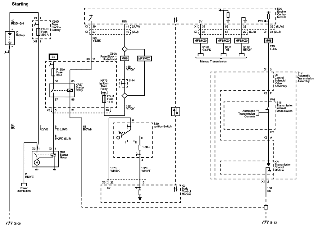
Brown Radio Illumination Dimmer Wire. 2006 Toyota Highlander Hybrid Electrical Wiring Diagram Service Manual.