It shows how the electric wires are interconnected and also can also reveal where components as well as components could be connected to the system. TYPES OF WIRING DIAGRAMS There are three basic types of wiring diagrams used in the HVACR industrytoday.
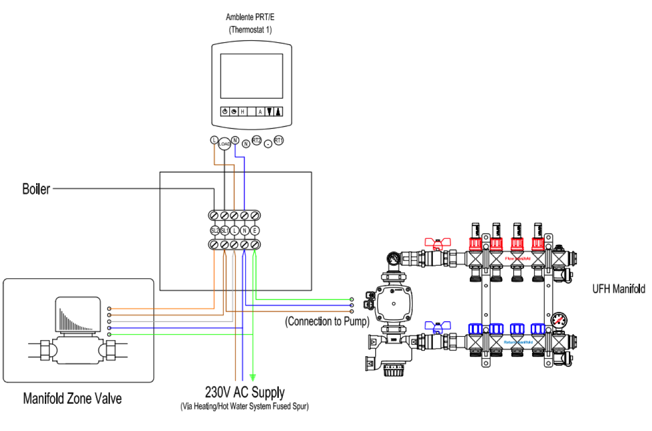
Using our wiring centres in your application means that the actuator boiler and pump connections are wired from a single point.

Heat meter wiring diagram. Carrier Hvac thermostat Wiring Diagram wiring diagram is a simplified up to standard pictorial representation of an electrical circuit. The first and most common is the ladder diagram so called because it looks like the symbols that are used to represent the components in the system have been placed on the rungs of a ladder. Meter basics Meters provide the data we need to calculate For more information see correct payments to participants of the Non-Domestic RHI scheme.
However as the refrigerant used in the Samsung EHS is R410A it is not able to physically heat above its critical temperature of 728C. The valve can be installed in the flow as per the diagram. The main supply is 120V AC in US and 230V AC in EU.
Click the icon or the document title to download the pdf. With the new built-in 2-way communication in MULTICAL 403 and a READy remote meter reading system it is now possible to perform remote configuration of the ultrasonic heat meters and reading of the log without direct access to the installation. A heat meter is made up of three independent parts.
Read Or Download The Diagram Pictures Meter For FREE Wiring Diagram at CROWDFUNDING-DONATEDEMOAGRIYACOM. If you dont have a second meter you wont get this cheap rate supply even if you have two rates on your bill. A wiring diagram is a basic aesthetic representation of the physical connections and also physical layout of an electric system or circuit.
Volume test is applied to all heat meters for q s q p 01 q p and q i flowrates By using standing start stop method and weighing devices. Its components are shown by the pictorial to be easily identifiable. The prescriptions related in the standard EN14346 must be respected when the - Superstatic 749 is installed.
Installation guide Thermal Energy Meter Superstatic 749. Depending on the test results for each meter calibration datas are set to the heat meter by using M_bus-Energy test. For this reason the heat pump cylinder comes with a 2 port valve and tank stat.
Contains all the essential Wiring Diagrams across our range of heating controls. Kamstrup ultrasonic heat meters are produced to MID Approval EN1434 a stringent European standard that ensures that the accuracy and quality remain constant so you can be confident that every meter is as good as the last. Heat Meter Wiring Diagram It is far more helpful as a reference guide if anyone wants to know about the homes electrical system.
All heat meters are installed to the test bench and M_bus cables attached to the test bench. Make sure you control the times and temperature your electric heating system comes on and off so you dont spend more than you have to. Many heating engineers do not install this valve.
This heat is then slowly released during the day but doesnt use any electricity during the day. Heat on 1 Circuit X 1 AC and WH X X 3 Heat on 1 Circuit and WH X X 2 Heat on 2 Circuits X X 3 Heat on 56 Circuits and WHAC Optional X X X 4 Additional notes. The ULTRAFLOW flow sensors use microprocessor technology and ultrasonic measuring techniques.
Heatmiser UH8-N The Heatmiser UH8-N is designed to be used in conjunction with our 12v thermostats. Discover the possibilities within flexible and easy remote configuration of heat meters for less hassle for both the utility and the consumer. Depending on its particular version and use heat andor cooling meter the energy meter must be fitted on the cold or hot pipe side of the.
A flow sensor also known as a flow meter which measures the flow rate of the liquid a temperature sensor pair which measures the. Our Wiring Diagrams section details a selection of key wiring diagrams focused around typical Sundial S and Y Plans. Read Or Download The Diagram Pictures Meter For FREE Wiring Diagram at CROWDFUNDINGDEMOAGRIYACOM.
A smoke or heat detector can be installed to the existing or new home wiring. Diagrams are available for all Warmup Thermostats whether you are installing it as part of a hydronic underfloor heating system a simple combination boiler configuration or even a multi-zoned central heating system. It shows the components of the circuit as simplified shapes and the facility and signal connections amid the devices.
Add single meter socket if member does not have a double meter socket. From this point forward ladder dia-. They give you heat and hot water on demand but need a 24-hour electricity supply.
Flow boilers do not supply domestic hot water so your hot water will still be provided through your hot water tank. What is a Wiring Diagram. This method of heating uses cheap night rate electricity which needs a second meter or a meter with 2 dials.
Our Wiring Diagrams offer easy-to- follow layouts along with clear wiring colors and a detailed legend to help you successfully connect a Warmup Controller with the heating system it is to control. Is the least efficient diagram among the electrical wiring diagram. In our basic wiring diagram a single or multiple heat and smoke detectors are installed in the home by connecting the live line or hot neutral ground and an interconnected wire to the alarm.
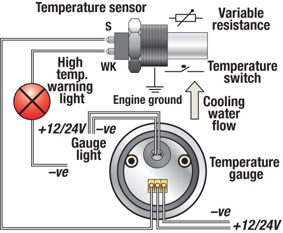
 Temperature Gauge Wiring Diagram Trailer Light Wiring Gauges Electrical Diagram
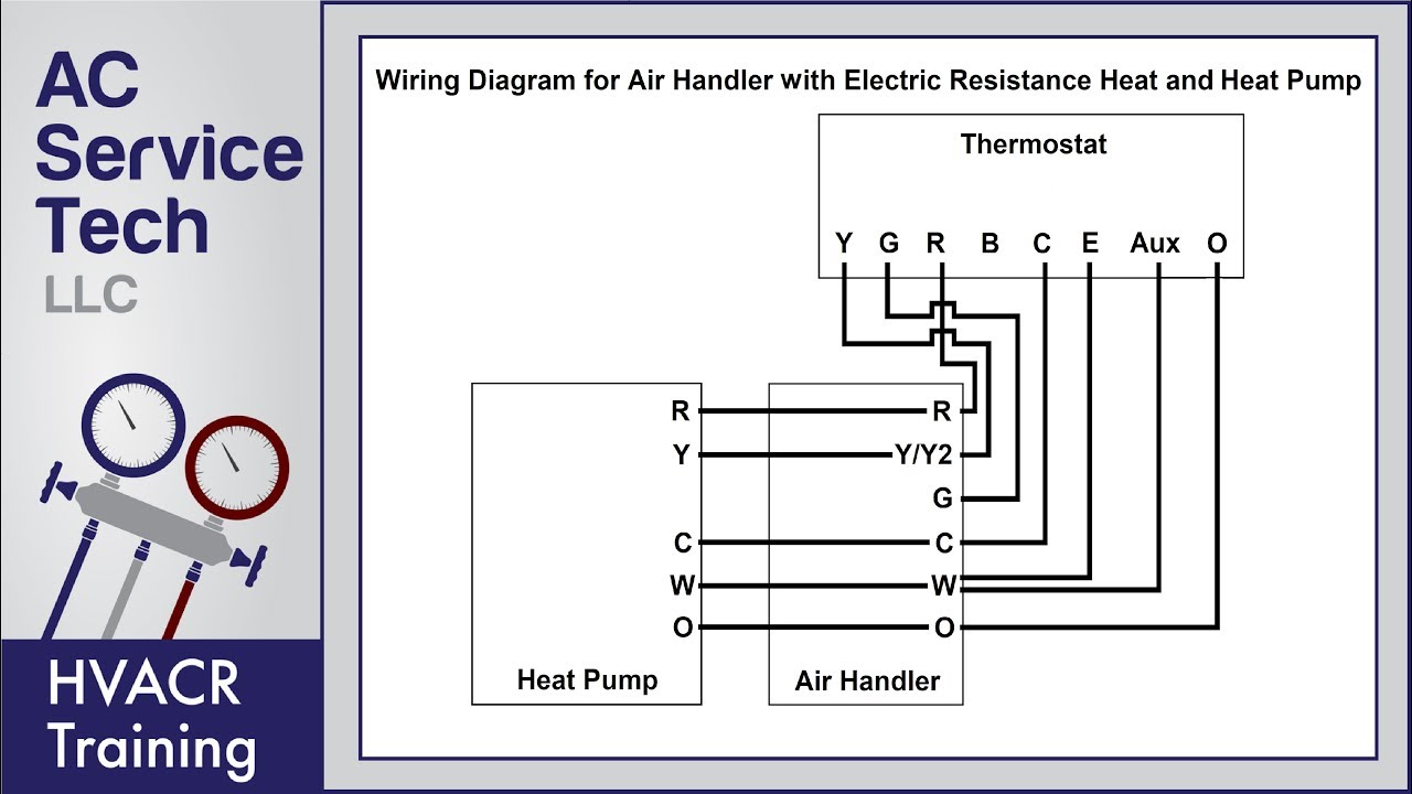 Thermostat Wiring Diagrams 10 Most Common Youtube
Pin On 10 Ft X 24 Ft Tiny House
 Refrigeration Pressure Switch Wiring Diagram Hvac Air Refrigerator Hvac


No comments:
Post a Comment